ISO 9001 · ISO 14001 · ISO 45001 · CE · UDEM · EAC · CQC
🇩🇪 Germany · Energy storage
Germany: 2 MWh Liquid-Cooled Containerized BESS
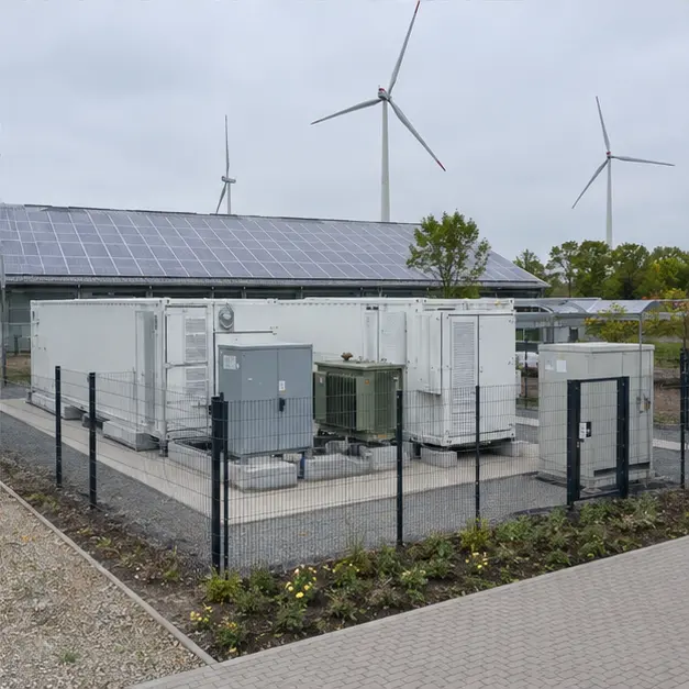
Reference configuration: 2 MWh liquid-cooled containerized battery energy storage system with PCS and transformer for industrial renewable-energy…
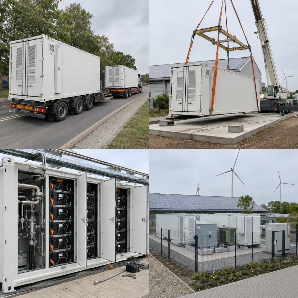
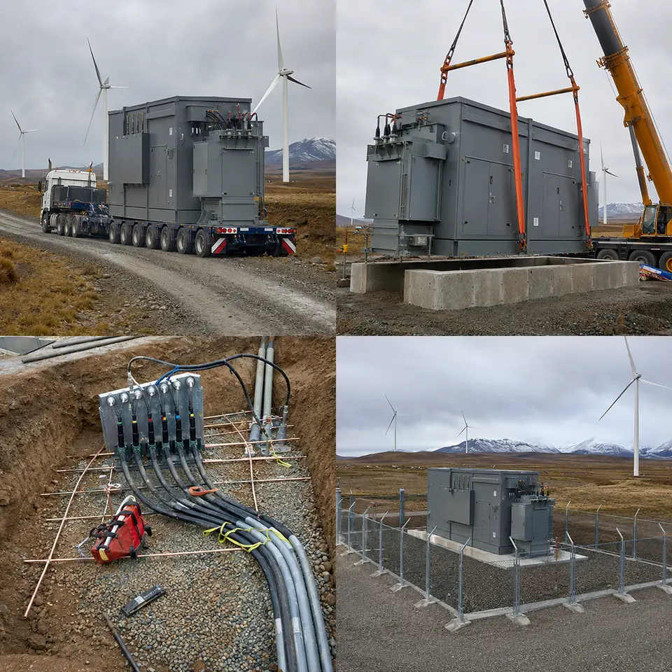
The four-stage sequence typical of a liquid-cooled containerized battery storage system for industrial renewable integration in Germany
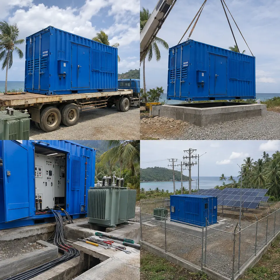
Representative project visualisation. Representative visualisation, not a delivered installation. Every image in this set is a representative rendering of a typical build for this equipment class. None of them is a photograph or documentary record of a completed project, and none depicts an actual customer, site, operator, grid operator, contract, energisation date, or third-party certification. All ratings, quantities and layouts shown are illustrative starting points that would be finalized against a genuine enquiry.
At a glance
Country
Germany
Application
Industrial renewable-energy integration, peak shaving and grid support
System
2 MWh liquid-cooled containerized battery energy storage system with PCS and transformer
Voltage
Battery DC bus to PCS; MV connection voltage fixed against the network operator's connection point
Frequency
50 Hz
Standards basis
IEC 62933 series (electrical energy storage systems), IEC 62619 and IEC 63056 (industrial lithium cells and battery systems), IEC 62477-1 (power conversion), IEC 60076 series with EU Ecodesign Regulation 548/2014 as amended by 2019/1783 (Tier 2 loss limits), VDE-AR-N 4110 for medium-voltage connection, VDE-AR-E 2510-50 for stationary battery storage installations, UN 38.3 and ADR for transport
Connecting a battery system to the German grid means operating inside one of the more explicit and demanding regulatory frameworks anywhere, and that reality has to shape the specification from day one rather than being retrofitted once equipment is already on order.
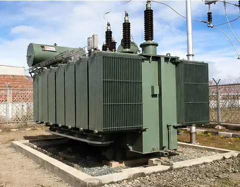
The transformer illustrates this most clearly. Every transformer placed on the EU market has to satisfy the Ecodesign loss limits, and the Tier 2 thresholds have applied since 1 July 2021. For a medium-power unit that translates into a mandated minimum peak efficiency index, reached through improved core steel and additional core and winding cross-section — which in turn means a bigger, heavier and pricier transformer than an equivalent rating built for a market without such loss rules. This isn't merely a paperwork requirement on a storage asset: the transformer sits directly in the round-trip efficiency chain, stays energised around the clock, and its no-load losses accrue hour after hour regardless of whether the battery is actually cycling.
Grid connection is the second driver. Once a storage unit ties in at medium voltage, VDE-AR-N 4110 treats it much like a generating plant: it must supply reactive power, ride through voltage and frequency disturbances, control active power, meet prescribed protection and interface-protection settings, and pass through a certification chain covering both the unit and the plant. These obligations shape which PCS is chosen and how protection is designed, so they need to be settled at enquiry stage, not discovered during commissioning.
Fire protection is the third. German practice for stationary lithium storage expects detection at both cell and module level, gas and smoke sensing that catches off-gassing before thermal runaway sets in, deflagration venting, a suppression strategy, and defined separation distances from buildings and site boundaries. Liquid cooling assists here by keeping cells within a tighter temperature band and pulling heat away faster than forced air could, but it brings its own obligations — freeze protection through a German winter, correctly specified coolant chemistry and concentration, leak detection, and redundant pumping.
How the system is built
Item
Description
Specification notes
Battery container
A containerized housing that integrates the battery racks, thermal management, fire protection and control systems
IP ingress and corrosion protection rated for outdoor European conditions; deflagration venting and separation distances fixed during the layout stage
Battery racks and modules
Lithium battery modules arranged in racks, each with its own disconnection and fusing
Cells and systems built to IEC 62619 and IEC 63056; voltage, current and temperature monitored at module, rack and system level
Battery management
A three-tier BMS spanning module, rack and system, handling contactor control and protection
Estimates state of charge and state of health, balances cells, and enforces hard limits that operate independently of the master controller
Liquid cooling system
A water-glycol loop built from a chiller, pumps, manifolds and cold plates at each rack
Glycol concentration matched to the site's coldest winter temperature; leak detection, redundant pumps, and monitored coolant flow and temperature; rack-to-rack delta-T held within limits to prevent cell divergence
PCS
Converts power bidirectionally between the battery DC bus and the AC system
Configurable as grid-forming or grid-following depending on the application; delivers and certifies the VDE-AR-N 4110 functions — reactive capability, ride-through, active power control
Transformer
Steps up voltage between the PCS output and the MV connection point
Built to Ecodesign Tier 2 loss levels; cast-resin dry-type where indoor placement and fire load are the concern, or oil-immersed with containment otherwise; impedance matched to the PCS
MV switchgear and protection
Handles MV switching, interface protection and metering at the point of connection
Protection and interface-protection settings per the network operator's requirement; metering arranged as the connection agreement specifies
Fire detection and protection
Combines gas, smoke and heat detection with alarming and the chosen suppression or containment approach
Tuned to catch off-gassing before thermal runaway develops; venting, suppression and emergency shutdown all interlocked with the BMS and PCS
Control and communication
An energy management controller interfacing with site loads, generation and the network operator
Communicates over Modbus TCP, IEC 61850 or IEC 60870-5-104; provides remote control and telemetry as required by the connection agreement
How installation unfolds
Overview — The four-stage sequence typical of a liquid-cooled containerized battery storage system for industrial renewable integration in Germany
This contact sheet walks through the four stages typical of this kind of build: transporting the container to site, lifting it onto its finished foundation by crane, inspecting the battery racks and cooling pipework, and the finished, fenced installation complete with PCS and transformer. The sequencing follows a simple rule — do the work that becomes hidden or hard to reach last. Foundation, cable ducts, earth grid and drainage are finished and surveyed before the container ever arrives. Interconnecting cable between the container, PCS and transformer is sized and run once actual positions are fixed. Only after mechanical and electrical work wraps up does coolant get filled, leaks get tested, and the first controlled charge take place — and the site isn't closed out until the fire detection and emergency shutdown chain has been proven end to end.
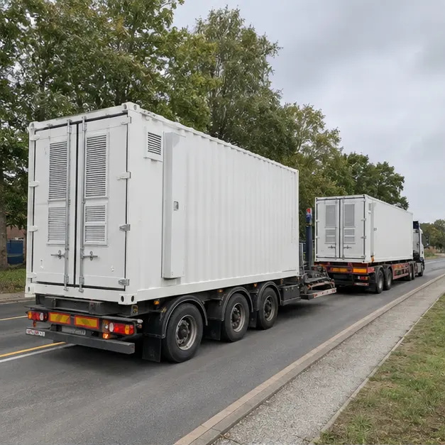
Delivery — Delivery of a liquid-cooled battery storage container of this type at an industrial site
A battery container ships as a dangerous-goods load. Lithium modules travel under UN 38.3 test certification and, on European roads, under ADR — typically kept at a reduced state of charge with the system electrically isolated, so documentation, labelling and the transport state of charge get scrutinised on arrival right alongside the hardware itself. Beforehand, the delivery route is checked for axle loading, headroom, gradients and turning radii. Once the container reaches site, it's inspected for transport damage, seal and louvre condition, water ingress, tripped shock indicators and any internal fixings that have shifted; the racks are examined for module movement and connector integrity, and the coolant circuit is checked for damage before it's pressurised or energised.
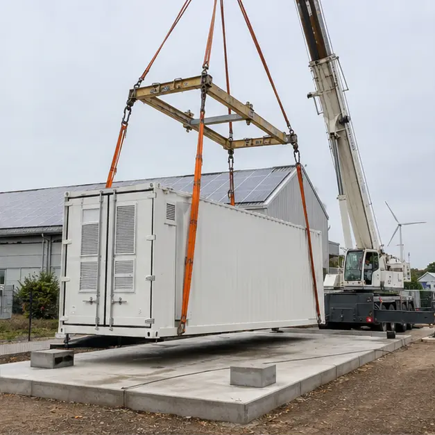
Placement — Crane placement onto a prepared foundation, characteristic of this type of containerized storage installation
Setting the container down is one lift of a heavy, evenly loaded, but tall structure. The crane lifts from the designated corner castings or lugs through a spreader beam, so slings never bear on the container walls, doors or roof-mounted cooling gear. Crane capacity is checked at the working radius, and outrigger bearing pressure is verified against what the ground can actually take. Level is confirmed before the container touches down — with liquid cooling, this stops being a cosmetic nicety and becomes a functional requirement, because an out-of-level container traps air in the coolant loop and skews flow between racks. Separation distances to buildings, boundaries and neighbouring equipment are checked against the fire-protection layout before the unit is finally anchored.
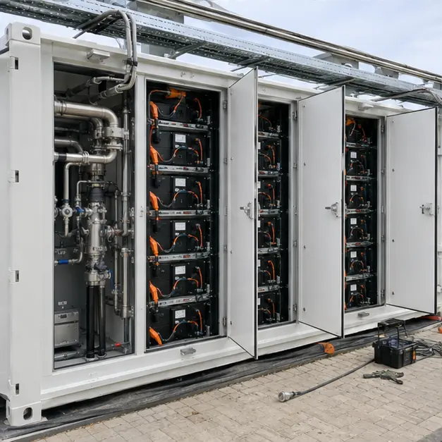
Internal work — Battery racks and liquid-cooling pipework typical of a containerized storage system of this kind
Work inside the container covers the DC connections, the coolant circuit, and the control and safety wiring. Each rack's DC connections is torqued to its specified value and marked, because a loose or high-resistance joint on a continuously loaded DC bus is both an efficiency loss and a fire hazard — DC arcs, unlike AC ones, don't self-extinguish. Polarity, rack isolation and fuse ratings are all confirmed before a rack gets closed up. The coolant circuit is charged with the specified water-glycol mix at whatever concentration the site's coldest temperature demands, then vented, pressure-tested and run to check that flow reaches every rack evenly — uneven flow shows up as temperature divergence between cells, and that shortens battery life. Leak detection, coolant temperature and flow monitoring, and the gas, smoke and heat detection loops are all functionally tested.
Completed configuration — A completed configuration of a 2 MWh liquid-cooled battery storage system with PCS and transformer
Ahead of energisation, the entire installation is verified link by link. Insulation resistance is measured on both DC and AC sides; earth continuity is traced from the container, racks, PCS and transformer all the way back to the site earth grid; and the transformer's ratio and vector group are confirmed, with its no-load and load losses checked against the Ecodesign declaration. Interface protection is injection-tested from end to end, and the grid-code functions demanded at the connection point are demonstrated in practice. The emergency shutdown chain is proved from every possible trigger — manual initiation, gas detection, a BMS fault — through to PCS shutdown and contactor opening. Commissioning then proceeds in steps: a low-power controlled first charge, verification of capacity and round-trip efficiency, and finally handover to the application's control mode.
Ways the specification can flex
On a similar enquiry, Millenium can size energy capacity and power rating to the intended duty — peak shaving, renewable balancing or grid support — and specify the C-rate, cycle life and warranty basis for whichever cell chemistry is chosen. Thermal management is available as liquid-cooled or forced-air, with coolant chemistry and freeze protection matched to the site's climate. The PCS can be offered grid-following or grid-forming, built with whatever reactive capability, ride-through and control functions the connection agreement calls for. The transformer is available as cast-resin dry-type or oil-immersed with containment, built to Ecodesign Tier 2 loss levels and with vector group and impedance matched to the PCS. Fire protection can range from basic detection and venting up to a full active suppression system. Enclosures can be specified by IP rating, corrosion category, coating and acoustic treatment, reporting over Modbus TCP, IEC 61850 or IEC 60870-5-104.
Information we need to quote this
A single-line diagram of the site showing generation sources, loads, and the proposed point of connection
The energy capacity and power rating needed, plus the duty profile — cycles per day, depth of discharge, and discharge duration
The priority application — peak shaving, self-consumption, renewable balancing, or grid services
Connection voltage, the network operator involved, and which connection guideline and certification requirement applies
Fault level at the connection point, the intended protection philosophy, and the interface protection settings required
Any reactive power, ride-through and active power control obligations tied to the connection point
The site's ambient temperature range, coldest winter temperature, and any acoustic restrictions
Fire-protection requirements, the separation distances available, and what the local authority expects
Footprint available, foundation layout, cable route lengths and duct positions
Preferred cell chemistry along with the required cycle life and warranty basis
Communication protocol, EMS interface, a points list, and details of any existing site control system
Site access route, permitted axle loading, crane capacity on hand, and delivery terms
Get in touch with us
Shanghai Millenium Industry Co., Ltd. (Millenium) — No. 555 Gangding Road, Lin-gang Special Area, China (Shanghai) Pilot Free Trade Zone, Shanghai, China.
Tel/WhatsApp/WeChat +86 175 0213 9434 · jensen@millenium-electric.com · millenium-electric.com
Every image in this document is a representative visualization of a typical configuration — not documentary evidence of a completed project.
Quotation
Quote a comparable Germany project
Tick what you can already provide — it is added to your message — then send the inquiry. Missing items are not a problem; we will ask.