ISO 9001 · ISO 14001 · ISO 45001 · CE · UDEM · EAC · CQC
🇰🇪 Kenya · Utility distribution
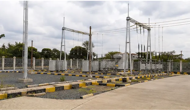
Kenya: 33 kV/11 kV Distribution Substation
Delivered 2023: 33 kV/11 kV distribution substation — transformer, RMU, LV switchgear, power distribution cabinets and related accessories for urban and…
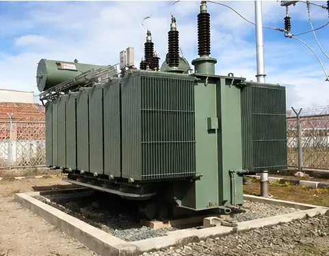
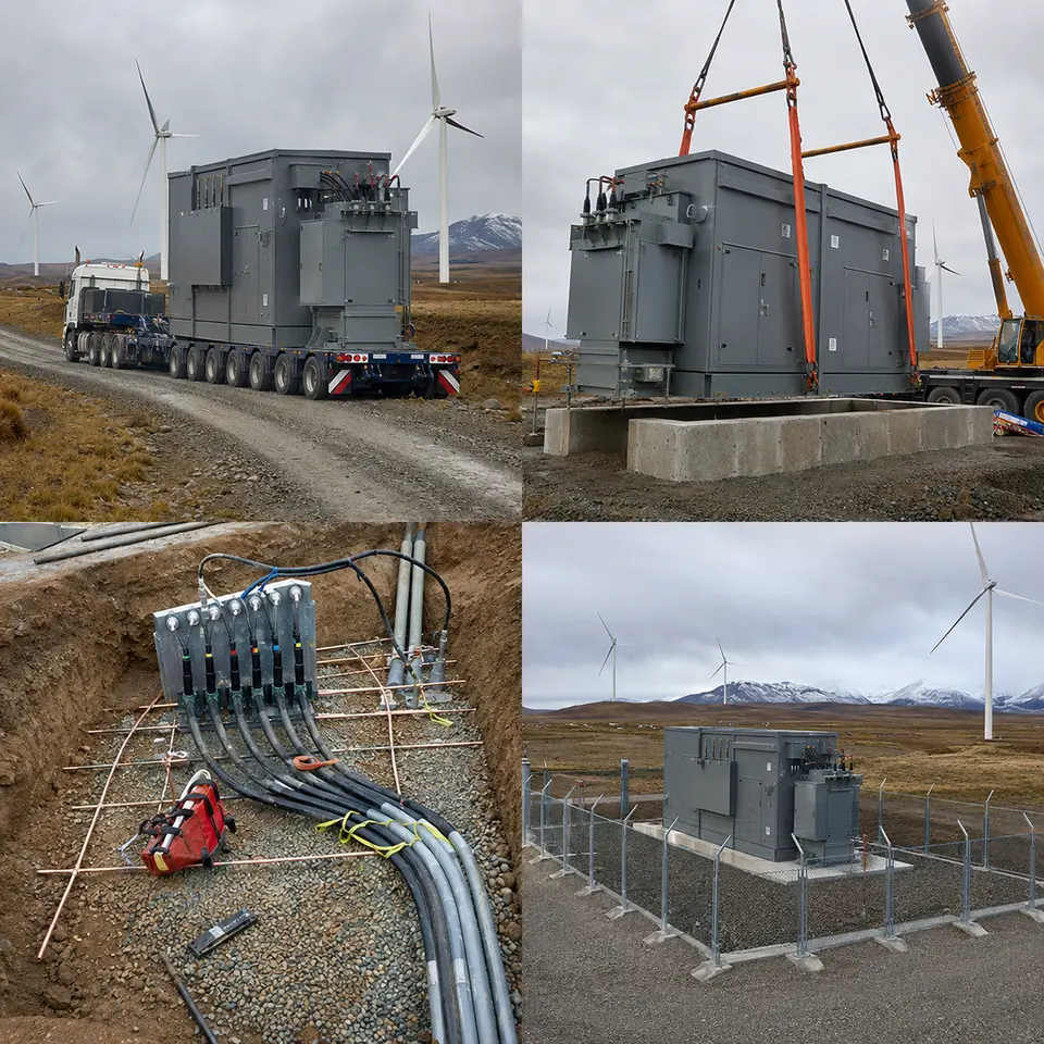
Power transformer set on its foundation on site
Delivered project. Millenium supplied the equipment for this 33 kV/11 kV distribution substation in Nairobi and supported the job with design input, on-site installation guidance and commissioning, bringing the station into service in March 2023.
At a glance
Country
Kenya
Location
Nairobi
Application
Urban and peri-urban distribution reinforcement
System
33 kV/11 kV distribution substation — transformer, RMU, LV switchgear, power distribution cabinets and related accessories
A step-down point from 33 kV to 11 kV in an expanding city has to satisfy two demands that pull in different directions: absorbing rising load without adding outages, and squeezing into a site that was never generous with space in the first place.
Supply at 33 kV in this setting is normally arranged as a ring or a looped radial feed. That pushes the design toward ring main unit switching, since it lets the substation take power from either direction and allows a faulted section to be isolated without taking the transformer off line. Open-air busbar arrangements at this voltage demand clearances an urban plot simply doesn't have room for, which is why a compartmented, metal-enclosed switching solution is the natural fit.
Move down to the 11 kV and LV side and the challenge shifts to fault energy and selectivity. Growing distribution capacity pushes up the prospective fault current seen at the LV board, so the switchgear's short-time withstand figure has to be picked against the transformer's impedance, not simply against the connected load.
Nairobi's climate layers on a third factor: persistent humidity, dust that varies with the season, and lightning striking overhead feeders. Getting insulation coordination, surge protection and enclosure sealing right matters here in a very practical sense, not just as a box to tick.
System configuration
Item
Description
Specification notes
Power transformer
33 kV/11 kV distribution transformer
Rating, vector group and impedance set by the project's load and fault-level study — see Details to confirm below
33 kV ring main unit
Metal-enclosed MV switching and protection for the incoming ring
Type-tested to IEC 62271-200; internal arc classification and cable-box arrangement matched to the incoming cable
11 kV / LV switchgear
Outgoing distribution switchboard
IEC 61439-1/-2 assembly; short-time withstand coordinated with transformer impedance and cable let-through
Power distribution cabinets
Feeder and auxiliary distribution enclosures
Segregation form, busbar current density and cable termination space defined by the outgoing schedule
Protection and metering
Overcurrent, earth-fault and transformer protection with associated CTs/VTs
Grading between incoming, transformer and outgoing stages; settings agreed with the network operator
Earthing system
Substation earth grid, equipment bonding and neutral earthing
Conductor cross-section sized for fault current and clearing time; step and touch potential checked against IEC 61936-1 practice
Surge protection
Arresters on exposed circuits
Rated voltage selected against system earthing arrangement and expected temporary overvoltage
Cable system and accessories
MV and LV cabling, terminations, glands, supports
Bending radius, screen bonding and gland sealing follow the accessory manufacturer's qualified method
Enclosure and civil interface
Foundation, cable trench, ventilation and access
Trench routing and pull-in points sized so cables are never bent inside the minimum radius
Installation sequence
The overview drawing lays out the substation: where the 33 kV feed enters, where the transformer sits, and how the MV switching room relates to LV distribution. This isn't a cosmetic exercise — it locks in cable lengths, and cable length in turn drives voltage drop, the screen-bonding approach and how much pulling tension a contractor can safely use before damaging the insulation. Access is decided here too: a transformer that can't be pulled out for repair down the line becomes a standing maintenance headache. Wall clearances, ventilation routes and where the earth grid sits relative to the equipment footprint are all settled before the first concrete is poured.
Transformer placement — Power transformer set on its foundation on site
Placing the transformer is the single riskiest lift on the project. Rigging uses only the lift points the manufacturer built in, and the sling geometry is arranged so the resultant force runs through the unit's actual centre of gravity — which sits toward the core and windings, not the geometric middle of the tank. Before the unit comes down, the plinth is checked for level; an uneven seating loads the tank base unequally and can throw off gasket compression at the cover and radiator flanges. Once it's placed, oil level, gas relay condition and gaskets are inspected, and the transformer is given time to settle before any terminations go on.
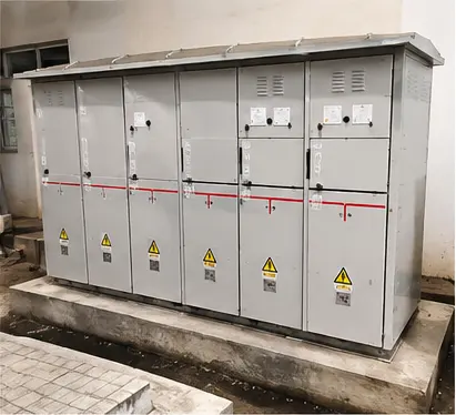
MV switching — 33 kV ring main unit installed and terminated
With the 33 kV ring main unit positioned, levelled and bolted down, the incoming and interconnecting cables are terminated. This step accounts for more MV installation failures than any other: the length of semiconducting screen cut-back, how clean the insulation surface is, and whether the stress cone seats correctly all determine whether the joint lasts. Cable screens bond to the RMU earth bar through a conductor sized for the expected earth-fault current. Interlocks between the switch, the earth switch and cable-compartment access are exercised and confirmed by hand, never assumed, before the compartment door is shut.
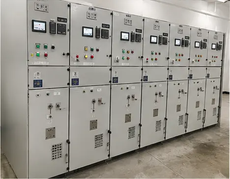
LV distribution — LV switchgear assembly installed at the substation
The LV switchboard goes together with sections aligned and bolted so the busbars meet naturally rather than being forced into place — forcing a joint into alignment leaves permanent stress behind. Every busbar and terminal connection gets torqued to spec and marked off. A joint that's under-torqued raises contact resistance, and it's contact resistance that eventually turns a rated connection into a hot spot; over-torque it instead and the bolt relaxes as it yields. Insulation resistance is measured phase-to-phase and phase-to-earth, and protection settings are checked against the grading study before the board is energised.
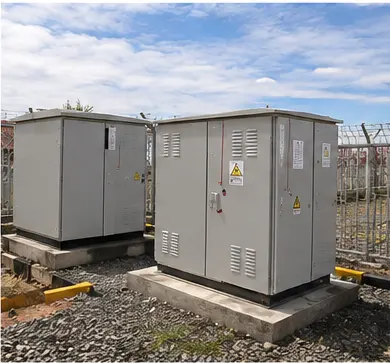
Feeder distribution — Power distribution cabinets installed and cabled
The distribution cabinets are set in place, bonded and cabled. Each cabinet's protective earth path gets proved by a continuity test back to the main earth bar, since a painted or powder-coated panel surface isn't a reliable conductor — bonding has to run through the dedicated earth studs and serrated washers instead. Gland plates seal the cable entries to the enclosure's stated IP rating, and single-core cables pass through non-magnetic gland plates to avoid induced circulating currents and the local heating that comes with them. Circuit identification and as-built schedules are finished here, not left until after the system is live.
Before switching anything on, the substation is proved as one complete system. Transformer ratio and vector group get verified, insulation resistance and — where called for — oil condition are logged, earth grid resistance is measured, and protection is tested end-to-end by injection so the relay, the CT circuit and the trip coil are all confirmed working together as a single chain. Interlocks, labelling, signage and access control are all checked off. Only then does the substation get energised, in a controlled sequence, with load brought on gradually while temperatures and readings are watched.
Specification options
For a comparable 33 kV/11 kV enquiry, Millenium can adjust the voltage ratio and tapping range, capacity, vector group and impedance, offer copper or aluminium windings, and provide oil-immersed or cast-resin construction with cooling from ONAN through ONAF, or AF for dry-type units. Insulation class, temperature-rise limits and overload capability can all be matched to site ambient conditions. Enclosures come in the IP rating and corrosion protection class the project needs, with anti-condensation heating and ventilation built in for humid climates. Protection and monitoring can range from conventional relays through winding-temperature indication, gas relay and oil-level contacts, up to full digital monitoring over IEC 61850, Modbus RTU/TCP or DNP3. RMU and LV assemblies can be extended, reconfigured or built to an alternative internal arc classification.
What we need to quote
Single-line diagram of the substation and its connection to the network
Incoming and outgoing voltages, tapping range and required vector group
Transformer capacity, expected loading profile and overload requirement
System fault level and required short-time withstand rating and duration
Neutral earthing arrangement and protection philosophy, with the grading study if one exists
Site ambient temperature range, altitude, humidity and pollution or salinity level
Utility or network operator specification and approval requirements
Number, size and type of incoming and outgoing cables, plus entry direction
Communication protocol and SCADA or monitoring interface required
Enclosure IP rating, corrosion protection class and paint specification
Civil interface: foundation and trench drawings, available access route and lifting equipment
Delivery terms, destination port, required documentation and test certificates
Quotation
Quote a comparable Kenya project
Tick what you can already provide — it is added to your message — then send the inquiry. Missing items are not a problem; we will ask.